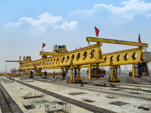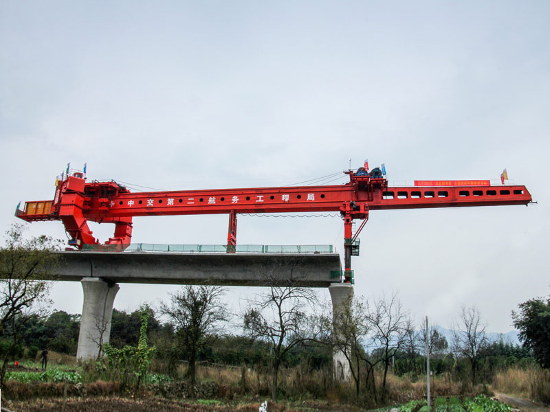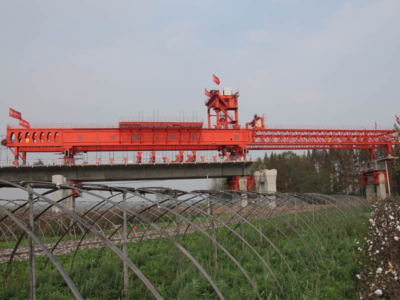
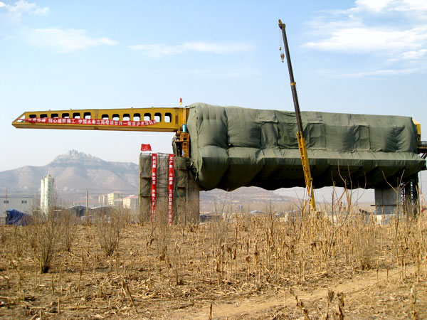
Upstroke Movable Support System


10. Tracing data and leaving factory data of Upstroke Movable Support System
● The tracing data of product is made up of contract, review file, drawing , calculation book of design, specification, installation project, raw material quality certificate, product quality inspection record, welding inspection report and purchased certificate.
● leaving factory data is made up specification, installation project, certificate and receiving report etc.
11. The installation method and steps of Upstroke Movable Support System
● Assemble the temporary supporting frame
● Install the front and rear support legs, longitudinal traveling auxiliary support legs
● Assemble the main girder
● Assemble the hydraulic and electrical devices
● Place the whole machine in the proper position
● Install the cantilever beam
● Assemble and hoist the base mould
● Install the side mould frame
● Adjust the base mould plate
● Assemble the side mould plate and poles
● Adjust the side mould plate
● Install wing mould plate
● Assemble the special-shape mould plate and pier top bulk mould
● Carry the pressure and load test
12. Checking methods after installation of Upstroke Movable Support System
Check the dimension, perpendicularity, pre-camber, deflection when the installation is done.
● The overall dimension: 62.5m(L) ×20.6m(W) ×5.6m(H above the bridge)
● The upper deflection of main girder: AF=(0.9/1000-1.4/1000)S
● Adjust the pre-camber to approach the standard of the instructions
● The main girder side curvature: AFP≤S/1200
● Assemble and connect the high-strength bolt according to the standard