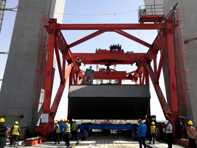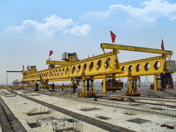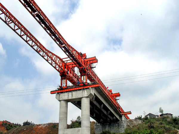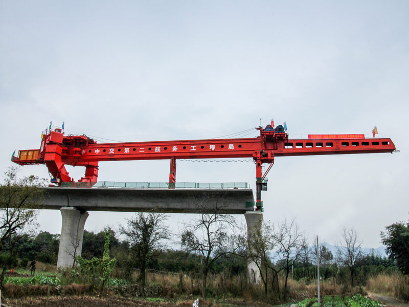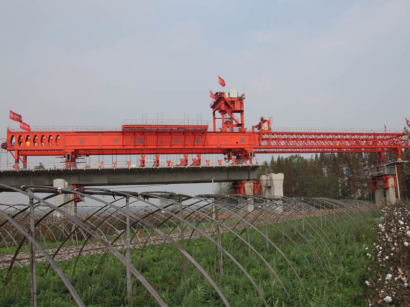
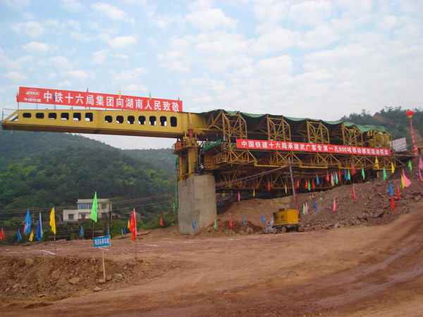
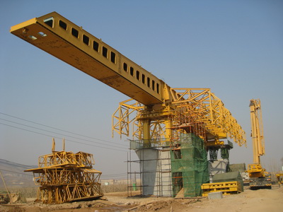
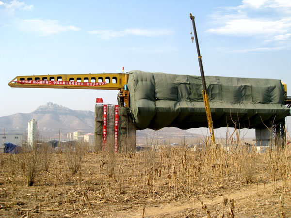
Upstroke Movable Support System
4. The design basis of Upstroke Movable Support System
MZ900s Upstroke Bridge Creating Machine in passenger transportation line project is designed according to the <<Purchase and Sale Agreement>>, the drawing of concrete box-girder, piers and abutment provided by customers and some national design standard in the field of machinery.
● << Crane Design Standard>> (GB/T3811)
● << Steel Structure Design Standard>> (GB50017)
● << Code for Design of Highway Bridges and Culverts>> (JTJ021)
● << The General Safety Technical Requirements for Engineering Machinery>> (JB/T6030)
● << Code for Construction and Acceptance of Electrical Appliance Installation Engineering>> (GB50256)
● << The General Technical Conditions for Hydraulic System>> (GB 3766)
● << Code for Construction and Acceptance of Steel Structure>> (GB50205)
● << Mechanical Properties of Fasteners—Bolts, Screws and Studs>> (GB 3098.1)
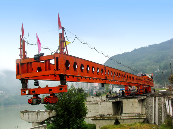
5. The video of Honeycomb beam Honeycomb beam Upstroke Movable Support System
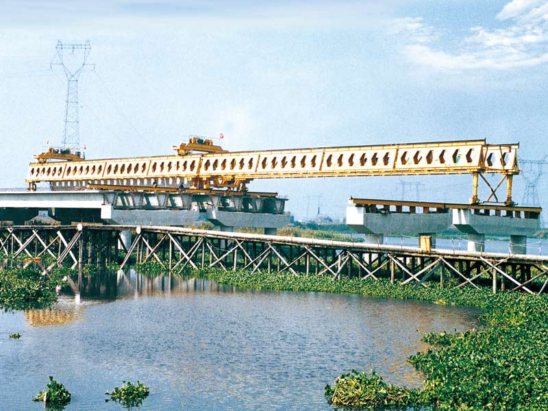
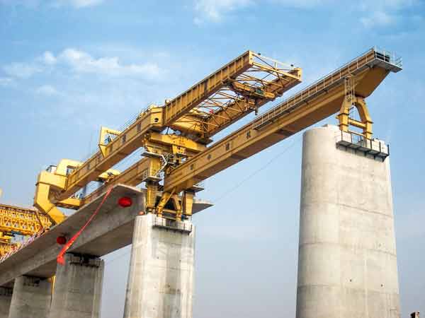
6. Main design requirements of Upstroke Movable Support System
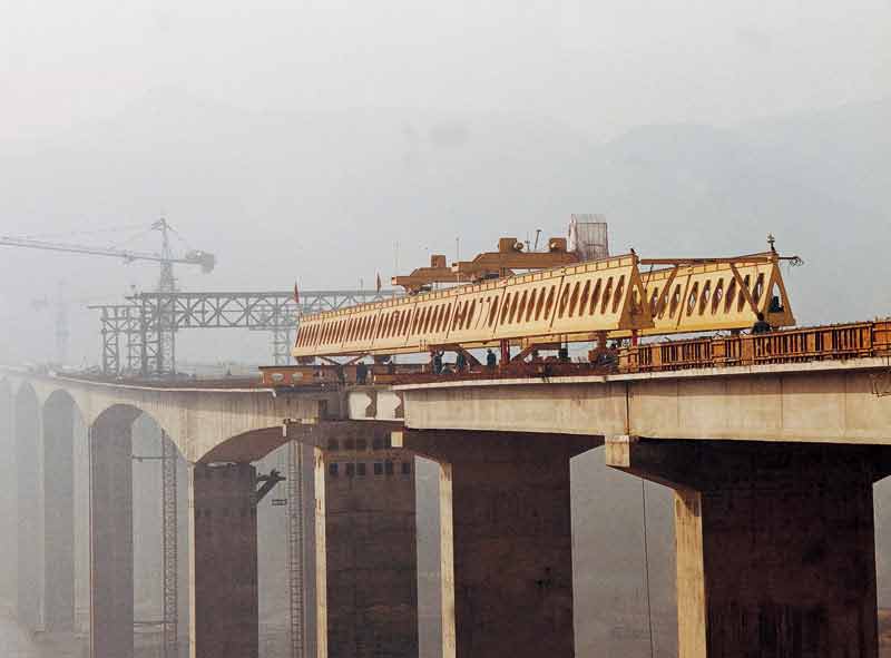
● The machine can meet the needs of the 32m, 24m full-span box girder erection in the railway passenger double line project.
● While the machine needs to erect the continuous girder or transferring, just to expand the side mould frame and base mould.
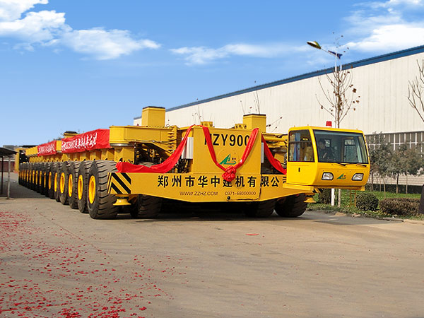
● The machine moves with the walking hydraulic jacking system, replacing the support legs with the steel rope traction method.
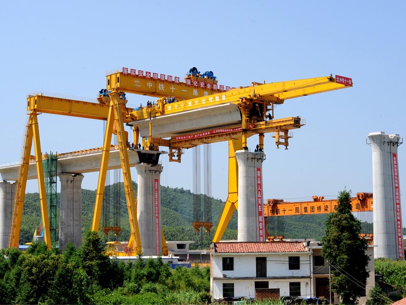
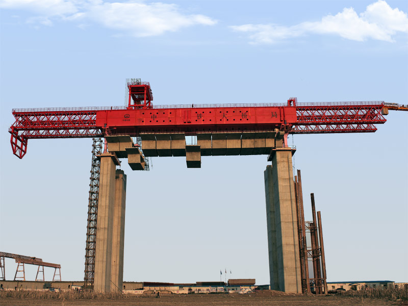
● The single main girder structure with a rigid and flexible support leg as the supporting.
● The weight-casting capacity: about 900t
● Max. anti force at working: 5805KN
● Applicable curve radius: R>2000m
● Applicable longitudinal slope/ transverse slope: 2%/2%
● The deflection of main girder: 1/700