Guidelines for gantry crane installation and disassembly
A flow chart of gantry crane operation
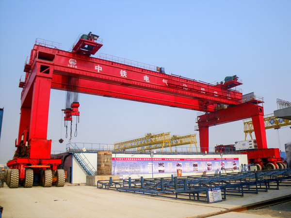
Because gantry crane is a special lifting equipment, installation, disassembly and lifting operations must be clear division of labor, unified command, to set up full-time operators, full-time electricians and full-time safety inspectors. There should be strict construction organization and measures to ensure the safety of construction. Operators must operate in strict accordance with the national safety technical operation regulations for hoisting machinery.
II. Installation flow chart of gantry crane
1. Preparation before construction
(1) The construction site is hardened in advance, the site is open and there is no obstacle interfering with the installation and construction, and the foundation of the crane working area is solid and reliable.
(2) The construction of the gantry crane line has been completed and qualified for acceptance.
(3) Construction personnel must be familiar with the construction site, familiar with the installation plan, technical personnel to do a good job in the construction process of technical safety disclosure.
(4) to cooperate with the installation of crane and personnel for qualification review and technical safety disclosure, cooperate with the machinery and tools for a comprehensive inspection.
(5) a comprehensive inspection of all the tools used for installation, and all the safety devices must be complete and reliable.
The safety belt, speed difference protector and safety rope used in the operation should be inspected and qualified.
All construction personnel must wear safety protective equipment.
The operating range is provided as a warning area, non-gantry crane installation and construction personnel are strictly prohibited.
2. General installation steps
Start → track reinspection → assembly of main girder → installation of lower beam → connecting legs and lower beam → integral lifting gantry crane → connecting legs and main girder → operation room installation → electrical system installation → safety device installation → complete inspection → no-load commissioning → load test → end
Specific construction procedures
Track reinspection
(1) the track should be fixed reliably, the bolt shall not be loosened, the pressure plate shall not be deformed, and the track surface shall not have cracks, scars and other defects affecting the safe operation;
(2) the two track gauge error is not more than 10mm;
(3) The longitudinal inclination of the top surface of the track is not more than 3/1000, and the height difference in the whole journey is not more than 10mm, and the relative elevation difference of two parallel tracks in the same section is not more than 10mm;
(4) the track joint adopts the butt arrangement;
(5) The height difference of the track joint and the wrong tooth should not be greater than 1mm;
Main girder assembled
The 12m span girder is directly lifted to the predetermined lifting position, and is directly lifted to the installation position by crane after the assembly of the supporting legs is completed.
The left half of the main girder with a span of 24 meters of 25 tons and 100 tons shall be hoisted to a predetermined position by a crane. After the position, the supporting pads shall be adjusted, and then the right half of the main girder shall be fixed by the supporting pads on both sides of the main girder. After the above completion, the main girder shall be connected, and then the main girder shall be monitored.
Walking under beam installation
The lower beam is hoisted to the track with the crane, and then the clamping rail device is tightened. The gearbox on the side of the trolley uses sleeper support pad, and the two sides of the walking beam are supported firmly with square wood, and the vertical of the walking beam is guaranteed.
Connect the leg to the walking lower beam
The supporting legs shall be hoisted to the end of the lower crossbeam by crane for installation. The flange shall have the factory number, and the bolt shall be tightened to pull the wind cable. Adjust the tightness of the hand hoist and measure the verticality of the corrected leg.
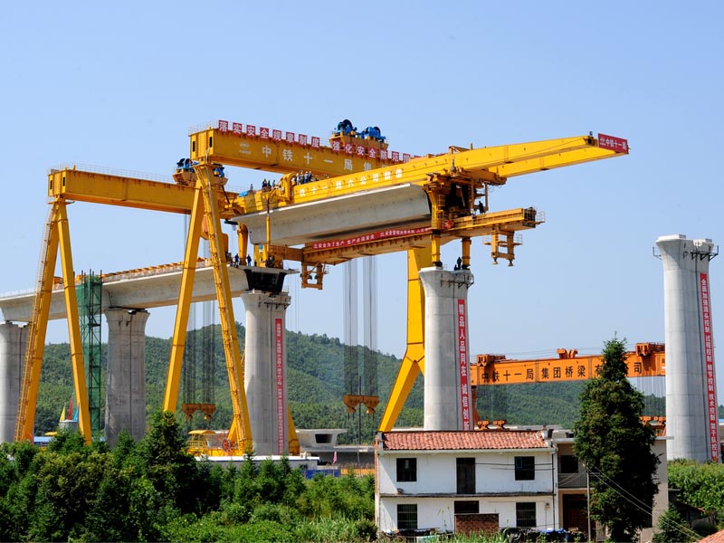
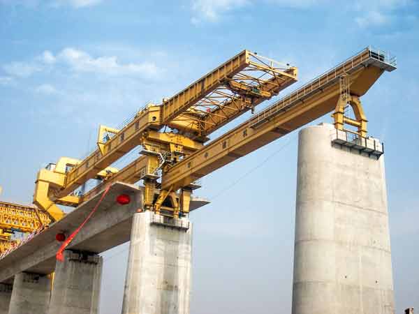
Main girder lifting
The main girder of 12-ton 12-meter span gantry crane is installed with a 30-ton crane to lift the main girder as a whole. The boom length of the crane is 17.3 meters and the working radius is 6 meters. The rated lifting weight is 13.65 tons, and the total weight of the main girder is about 10 tons.
The main girder of 25 tons and 24 meters span gantry crane is installed with 80 tons crane as a whole to lift the main girder. The boom length of the crane is 24 meters and the working radius is 6 meters. The rated lifting weight is 32 tons, and the total weight of the main girder is about 22 tons.
The main girder of 100-ton 24-meter span gantry crane is installed with two 80 ton cranes, the crane arm is 18 meters, and the working radius is 6 meters. The rated lifting weight of a single crane is 34.3 tons, the total lifting weight of the two cranes is 68.6 tons, and the total weight of the main girder is about 52 tons. The beam lifting mode of the two cranes fully meets the lifting requirements.
Before hoisting, check the working position and working radius of the crane, check the hoisting point of the main girder and the Angle position of the binding point, and remove all obstacles. When lifting a bicycle, the crane is only trained by one person in chief, and the crane is supervised by one person. The crane is lifted 10cm off the ground, and the crane is observed for 5 minutes. The weight of the bridge and the load bearing rate of the crane are rechecked and qualified, and the main girder is landed in place. After re-testing the crane brake system and checking that there are no abnormal problems, the crane can be lifted. Command personnel and monitoring personnel should observe closely to keep the whole main beam lifted horizontally and smoothly. When the main beam is lifted to a position higher than the upper part of the supporting leg, stop lifting, and turn the crane to connect the connecting flange of the supporting leg and the main beam directly. During the whole hoisting process, the crane's lifting rope and hook should be kept upright at all times.
When two cars and lintel set always refers to the 1, crane guardian 3 people, at both the crane selection is symmetrical, balanced two car hoisting, obey the commander password hoisting up about 10 cm from the ground at the same time, the static observation for 5 minutes, check whether the car hoisting equilibrium, wire rope Angle whether meet the requirements, and check the brake system, after the examination without exception crane lifting, The command personnel and the monitoring personnel should observe closely and keep the lifting speed of the two vehicles consistent so that the whole main girder can be lifted horizontally and smoothly. When the main girder is lifted to a position higher than the upper part of the supporting leg, stop lifting and turn the crane to connect the connecting flange of the supporting leg and the main girder directly. During the hoisting process, the movements of the two vehicles should be consistent and coordinated.
Installation of Operation Room
The operation room is hoisted to the design position by crane, and connected after accurate alignment.
Installation of electrical system
Connect the cables from the operation room to the two walking beam motors in turn, reserve the cable connectors for the other motors and safety devices respectively, and connect the reel cables to the operation room and the secondary plate.
Perfection and adjustment of safety devices
Gantry crane safety devices mainly include lifting weight limiter, hook height limiter, line spacing, and rail and end a gear, adjust the loading-capacity limiter the comprehensive error of plus or minus 5%, according to error of 5% or less, adjust the line stop, at each end to its limit position from 2 meters and adjust the hook height limit, its action position of main girder of about 2 meters.
3. Debugging the whole machine
Preparation and inspection before test run
(1) Check the whole machine according to the size and technical requirements of the drawing: whether the fasteners are firm, whether the transmission mechanism is accurate and flexible; Whether the metal structure is deformed, whether the wire rope is wound correctly and whether the rope head is tied firmly.
(2) check whether the crane assembly meets the requirements.
(3) check the insulation resistance of all electrical systems and all electrical equipment with a megameter; Cut off the circuit, check whether the control circuit is correct and whether all the moving parts of the control equipment are flexible and reliable, and lubricate if necessary; Rotate crane parts by hand, there should be no jamming phenomenon.
No load test
After the above inspection, the whole machine has been normal, no jam phenomenon, can be carried out no load test. Here are the steps:
A. Lifting car test: no-load electric hoist runs back and forth along the rail car for three times. At this time, there should be no obvious skid of the wheels, and the wheels should brake smoothly and reliably.
B. Lifting and lowering of the empty hook: make the empty hook rise and fall three times each, and the lifting limit should be accurate.
C. Stop the electric hoist at the root of the main beam and make the cart walk slowly along the full length of the longitudinal track twice to verify the track. Then walk three times at the rated speed to check the working quality of the operating mechanism. When starting and braking, the wheels should not skid and run smoothly.
Load test
When the no-load test is normal, the load test is allowed. The load test is divided into static load test and dynamic load test.
Technical requirements for load test
A. The welding and bolt connection quality of crane metal structure should meet the technical requirements.
B. The strength and toughness of mechanical equipment, metal structure and sphanger shall meet the requirements.
C, the brake action is flexible, the reducer is noiseless, the work is reliable.
D. The lubrication part is well lubricated, and the temperature rise of the bearing shall not exceed the provisions.
E, each mechanical movement is stable, no intense vibration and impact. If there is any defect, it should be repaired before testing.
[Static load test]
Electric hoist lifting rated load, after several times on the main beam, the electric hoist to the middle of the span, lift the weight to a certain height, stand for 10min, at this time measure the main beam deflection. Such a continuous test for three times, and the third time after unloading the load, there shall be no residual deformation of the main beam, each test time shall not be less than 10min.
After the above test, a test run of 20% overdetermined load can be carried out. The method and requirements are the same as above.
[Dynamic load test]
After the static load test is qualified, the mobile load test can be carried out.
The electric hoist lifts the rated load to do repeated lifting and descending braking test, and then starts the fully loaded electric hoist to walk back and forth along the track for 3~5 times. Finally, the full load of electric hoist will be opened to the root of the door frame, so that the crane at the rated speed and the cart track back and forth 2~3 times, and repeatedly brake and start. At this time, the brake, limit switch and electrical operation of the mechanism should be reliable, accurate and flexible, the wheel does not slip, the frame vibration is normal, the mechanism runs smoothly, and there is no residual deformation of the mechanism and the frame after unloading.
The above test results are good, the overload test of 10% can be done, the test items and requirements are the same as above. After passing the test, it can be used only after passing the inspection by the professional department.
III. Dismantling flow chart of gantry crane
1. Preparations before demolition
(1) Clean up the demolition site, ensure the demolition process barrier-free, demarcate the demolition scope and set up a police cordon to send special person to supervise.
(2) The automobile subgrade is flat and the road is free of obstacles, and the subgrade box is laid smoothly.
(3) set the main girder after the removal of the position on the ground, and square wood mat flat, for the other side of the main beam.
(4) Clamping rail clamps, sleepers are used to pad the crossbeam of 2 groups of walking mechanisms, respectively. In the upper part of the four supporting legs, wire rope and chain hoist are used symmetrically to pull the wind rope on the weight of 5T, and the force is equal. The Angle between the wind wire rope and the ground can not be greater than 45°.
(5) Cut off the power supply and remove the wire interface between the operating room and the trolley walking mechanism and the limiting device, and arrange and mark the cables.
⑥ in the leg and the main beam connection face down 1.5m, set up the work platform, the construction platform should be covered with bamboo ba and set up two railings, railings height is not less than 1.2 meters, platform width is not less than 500mm, bearing capacity is not less than 150kg/㎡.
⑦ The use of the crane, wire rope, shackle and other tools to do a comprehensive inspection, to ensure that good, gantry crane demolition crane selection and installation of the same crane.
(8) Safety education should be carried out for the personnel involved in the dismantling operation, the dangers and operational requirements in the dismantling process should be informed, the corresponding safety protective equipment should be equipped, and the dismantling work of the gantry crane should be carried out only after all the preparation work is in good condition and the dismantling conditions are met.
2. Removal steps
Overall disassembly steps: start → disassemble cable interface → main beam removal → operation room removal → leg removal → walking mechanism removal → rail removal → end
Remove cable interface
A. Before dismantling the cable, the hook should be received to the top end;
B. The 10T electric hoist is received at the rigid leg;
C. Cut off the main power supply, remove the cable interface of each limit device in the operation room (electric hoist cables are not removed first), and arrange and mark each cable. Receive the cable to the operation room;
Main girder demolition
A. Different cranes should be selected for different dead weights of main girders. The tonnage of the crane for disassembly is the same as that of the crane for installation.
B. After slowly lifting the steel wire rope, pull the rope at both ends of the main girder and dismantle the connecting bolt between the main girder and the supporting leg.
C. After all the connecting bolts are removed after inspection, the crane is slowly lifted to a position 5cm away from the supporting leg and stops lifting. Check the supporting leg and braking conditions of the crane again, and then start lifting the main girder after confirming that it is normal and the rotation direction drops to the specified position; When 12 tons and 25 tons of gantry cranes are dismantled, 1 general commander and 1 observer shall be set; when 100 tons of gantry cranes are dismantled, 1 general commander and 3 observers shall be set. During the whole dismantling process, the lifting rope and hook of the crane shall be kept upright at all times.
D. The removed box-shaped solid girder must be padded flat and solid with sleepers, which are distributed symmetrily, and the stability of each section of the bridge after the disintegration of the bridge must be considered.
E. Remove the electric hoist on the box-shaped solid belly beam.
3. Demolition of operation room
(1) Before dismantling the operating room, the doors and Windows should be closed, and the glass should be pasted with shockproof paper;
(2) first, the crane will operate room hanging, with the chain hoist operation room connected to the top of the ladder and the fixed lifting point on the rigid leg tension. The welding points are then cut open with wind welding, and the escalators and platforms connected to them are cut off one by one, and then hoisted to the ground.
4. Remove the supporting leg
(1) with steel wire rope, double head tied in the upper part of the leg symmetrical Angle, and in the corner of the bar with Angle protector to be protected.
(2) Use gas cutting to cut the railings and ladders connected with the walking mechanism and the rigid legs, and pull the rope.
(3), slowly lift rope, rope hoisting straight after removing the leg joint with walking mechanism of connection bolt nut, after the completion of the demolition continue to slowly lift travel mechanism ensure leg and 5 cm apart after check leg connected to the walking mechanism, through inspection connectionless enough when walking to dismantle and connecting bolt screw and against the wind line.
(4) Raise the hook, put the rigid leg down on one side of the plane of the rigid leg on the ground, and flatten it with square wood.
5. Removal of walking mechanism
(1) The center of gravity of the walking mechanism is about 2/3 of the length. The wire rope and shackle are installed on the walking mechanism, relax the clamp rail pliers, pull the rope, and lift the walking mechanism off the track.
6. Railway and rail removal
(1) Remove the rail pressing plate bolt first, and pad the rail 5cm high with the lever.
(2), each rail is hung to a place, put in a tidy pile, pad the head.