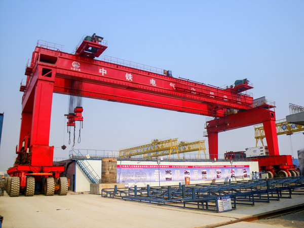
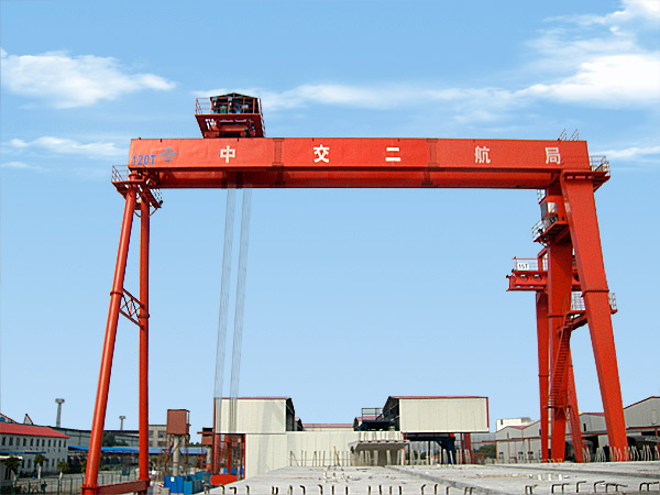
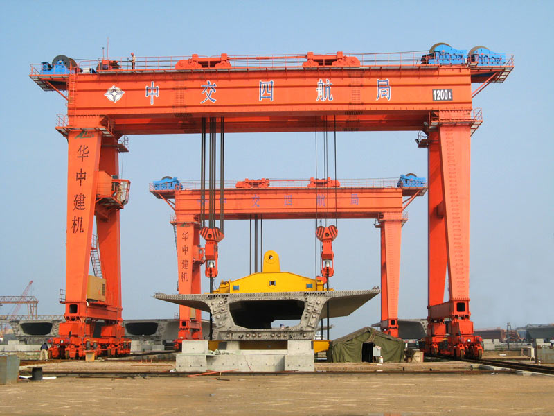
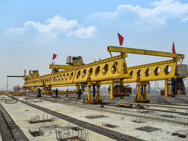
The main parts of the overhead crane
The overhead crane includes four major parts: the body structure, the trolley (lifting and traveling mechanism), the crane traveling mechanism and the electrical equipment.
The lifting mechanism, trolley traveling and crane traveling mechanisms are the three working mechanisms of the crane. Each mechanism is equipped with a sole motor for the respective drive.
The 5t and 10t crane is the single-hook overhead crane with one set of hoisting mechanism. The 16/3.2t and 50/10t crane equips 2 hooks with the main and auxiliary separate lifting mechanisms. The main hook is to lift the heavier objects. For the auxiliary hook, not only lifting the lighter objects but also complete the main hook overturning coordinated with the main hook in the rated loading range. One is must be noted that the hosting of the two hooks at the same time is prohibited. If they are operating simultaneously, the weight of the hoisted object are not allowed to exceed the lifting capacity of the main hook.
(1) Steel Structure
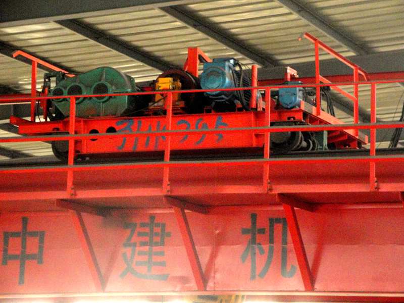
The steel structure part includes the bridge structure, trolley structure and operating room. The bridge structure consists of the double box type main girder, two box type end girders and path platforms on both ends of the main girder. Lay the trolley track on the top surface of the main girder. Install the crane traveling mechanism on the one side of the platforms, the trolley conductive slip lines were installed on the other side of the platforms. Equip with the guard rail on the outside the platform to protect the safety of the maintenance personnel.
Carry the rigid connection between the main girder and end girder. The middle points of the two end girders are the removable parts with bolt connection. In this way, the whole machine can be divided into two parts to transport and installation.
The trolley structure is welded by the steel plate on which equipping with both lifting mechanism and trolley traveling mechanism. The operating room was hung on the bottom part of the structure which was equipped with the electrical control equipment for the crane operation.
(2) Crane Traveling Mechanism
The four traveling wheels of the crane were installed on the two sides of the two end girders. There are two driving wheels and two driven wheels. The drive mechanism of the driving wheels was installed on the path platforms. Here we adopt two sets of symmetrical and independent drive devices which we call it “the respective drive”. Also we introduce the arc gear reducer whose loading capacity is higher than the same type of involute profile. All the mechanisms adopt the rolling bearing and A.C magnetic block brake.
The gear coupling connection applies to the body parts. In this way, even if the tolerance produced in the manufacturing and installation process or the components deformation caused by the deformation of the bridge structure due to the loading, the operation of the mechanism will not be affected because the coupling connection device can make the amendments.
The wheel axle of the driving and driven wheels bears on the angular bearing box which is facilitate to disassemble and repair.
(3) Lifting Mechanism
The lifting mechanism was installed on the top surface of the trolley structure. If there is only one hook, it equips with a set of drive system. If there are main hook and auxiliary hook, it equips with two sets of independent drive.
The operating procedure of the hoisting mechanism is the high-speed rotation of the dedicated motor for YZR-type crane to drive the involute gear reducer by the gear coupling. The low speed shaft of the reducer rotates the reel drum with the steel rope. Only control the forward and reverse rotation of the motor, can the hoisting mechanism take effect.
In order to ensure the safety and reliability of the hoisting mechanism, we install the brake on the high-speed shaft of the reducer. A up stopper was equipped on the one side of the bearing housing of the bearing reel which is a safety device when the lifted objects approach to the limit position.
For example, the crane for lifting the molten and hot metal must be equipped with two sets of the independent brakes, weight limiters and some different forms (usually the hammer and rotary) of dual-limiters of up stopper to control the different circuit devices. If the lifting height of the crane is higher than 20m, the down stopper of limit position needs to be installed according to the actual requirements.
(4) Trolley Traveling Mechanism
The trolley traveling mechanism is that the motor drives the vertical involute gear reducer. The low speed shaft of the reducer is connected with the driving wheels of the trolley structure in the means of concentrating driving. The motor adopts the shafts spreading from both ends and the brake was equipped on the one side of the shaft.
(5) Other Parts
A; The buffer
Equip with the crane spring buffer on the both sides of the end beams of the crane. And the trolley spring buffer was equipped on the bottom part of the trolley structure. All these measures is to reduce the collision impact caused by the two cranes with the same span or the crane and trolley travel to the limit position.
B; The gear rack of the crane conductive line
In order to prevent the sling or the steel rope colliding with the high voltage power supply when the trolley travels to the limit position, we place the conductive line gear rack on the bottom part of the two main girders of the bridge structure where is near from the power supply.
C; The crane conductive frame
The crane conductive frame was mounted on the bottom part of the main girders of the bridge structure. Through the three sets of the collector delay on the conductive frame, the power lines supply the power for the entire crane.


