How to install the crane rail?
The crane rail installation is a field between the mechanical and civil engineering construction projects. The crane rail installation will have a direct impact on the quality of crane operation. The crane rail produced by ZZHZ (Zhengzhou Huazhong Construction Machinery Co.,Ltd) is based on the customer’s requirements. Also its installation is in line with the site’s geological conditions and usually takes the 43KG/M model. The bearing capacity of foundation and track should be able to meet the site needs. Meanwhile equip with the sound grounding line to guarantee the electricity safety.
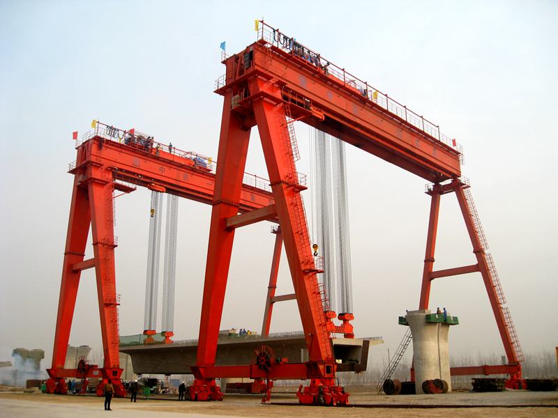
Regarding the crane made by ZZHZ, while the cart brakes, it produces a vertical thrust; if the trolley brakes, it produces a horizontal thrust; also during the cart and trolley brake at the same time, it produces a synthesis thrust and then makes a diagonal thrust for the rail. If the installation of one side of the rail is generally higher than the other side, the overall crane will move to the lower side, thus increasing the lateral force borne by the rail which will lead to the “bite rail” phenomena. Furthermore it will result in the collision accidents.
At present, the rail connection methods are plate fixation, hook bolts fixation and so on.
1, The rail includes the crane rail, railway rail and square steel. For the rail, its top is convex, the bottom is a flat plate with a certain width which increase the contact surface with the base; also the cross-section is ‘I’ type which owns the good strength for bending-resistance. The square steel can be seen as flat-top rail, due to wearing the wheel seriously, it’s usually adopted to the crane with light lifting capacity, slow traveling speed and less operation frequency.
2, The installation type of crane rail
2.1 The joint connecting seam of the crane rail is usually 1-2mm. In the installation process, if it is in the cold area or the temperature is below the normal and the difference is up to 20℃, consider the temperature compensation method and keep the seam 4-6mm.
2.2 The rail connecting head can be straight or the 45 º oblique joints, the oblique connector can make it a smooth transition when the wheel travels the joints.
2.3 The lateral dislocation and height difference in the jointing position of the rail shall not be more than 1mm.
2.4 The preparations before welding. Check carefully the groove face and clean the oil, dust and other sewage around it until the metallic luster exposing before welding the rail joints of the MG crane. Based on the principles of equivalent strength to match the Alkaline electrode.
2.5 For the rail joint, the welding sequence is from bottom to up, from rail bottom to rail waist, welding layer by road and weld around finally. Prepare the temporary check plate to fix the rail before welding the joints.
2.6 The cautions in welding process
For the each weld wave in welding process, especially welding the rail bottom, try the best to finish the task with one piece of electrode and avoid welding off. The welding direction should be opposite for the front and rear layer. The welding work should be continuous for the joints to guarantee the rail end is welded in a high temperature (300℃-350℃). After welding, when the stress relief heat treatment has done and the cooling is still not finished, take measures to prevent rain or other wet objects. The heated copper plant can be picked down to drown into water to cool down for using next time.
2.7 The polished treatment for rail joints
When the welded joints of the rail have carried the stress relief heat treatment and cool down to the normal temperature, the polished treatment should be done for the rail surface and both sides. If the welding flush is too large, do the polished treatment with an abrasive wheel polisher until it is in a level with the rail head, finally polishing the surface.
3, The rail girder installation requirements before laying the rails
3.1 The requirements for concrete rail girder
A, During the track beam production process, we must ensure that the reserved bolt hole location deviation along the horizontal and vertical directions≤5mm. The diameter of the bolt hole needs to be 2-7mm larger than that of the bolt. The top-surface of the beam should be smooth and not wiping with pressure.
B, The track beam misalignment must meet the following requirements, otherwise adjust the track beam before leveling with the concrete.
a, The design positioning axle deviation of beam center≤5mm.
b, The elevation deviation of the top surface of the beam should be 10mm-5mm.
c, The displacement deviation of the reserved bolt hole and beam center≤5mm.
C, The construction requirements of the concrete leveling layer
a, The thickness of the concrete leveling layer is 30~50mm.
b, Examine the installation deviation of the track beam according to the requirements before constructing the concrete leveling layer. Adjust the track beam if there are some conditions not complying with the requirements.
c, According to the actual elevation height of the track beam surface, identify a suitable surface elevation height of the concrete leveling layer. Set up a reference point for controlling the elevation height every 2.4-3.0m along the track beam.
d, The surface of the leveling layer must be leveled and polished. Forbid having the phenomena of uneven stones and concave, not allow to leveling with the way of laying another layer of concrete.
e, Mixing the concrete with the mechanical facility. Do the maintenance while the construction. When the concrete block has approached 75% strength design value, then begin to install the rail.
3.2 The requirements of the steel track beam
A, The perpendicularity of cross-track beam≤h/500, h for the height of track beam
B, The lateral bending gradient of the track beam≤l/1500, and net 10mm, I for the length of the track beam
C, The arch in vertical direction of the track beam≤10mm.
D, The design positioning axle deviation of the track beam≤5mm, adjust the positioning before installation if there is something not comply with the requirements.
E, The top height difference within the same cross-section of a track beam at support≤10mm, others≤15m.
F, The top height difference between the adjacent track beam≤1mm, the central lateral dislocation≤3mm.
4, The width between the rails is decided by the span of the crane. The rail longitudinal slope is no more than 1%. Inspect the cart driven power and the overall stability if it has exceeded the above-mentioned value. If it doesn’t comply with the requirements, adjust the slope before putting it into use. Both sides of the rail require in the same level correspondingly, the joints are stable to make the crane travel smoothly. Equip the traveling limit switch on the both ends of the crane rail.


